
The Leach Model: Accurate Voice Coil Inductance Modelling
Common tools treat voice coil inductance as a simple inductor - or ignore it entirely. The Leach semi-inductance model gets it right.
Contents
If you've compared a measured impedance curve to a simulated one and the high-frequency end doesn't match, voice coil inductance modelling is almost certainly the reason. This post explains why an ideal inductor gets it wrong and what the Leach model does instead.
The problem with ideal inductance
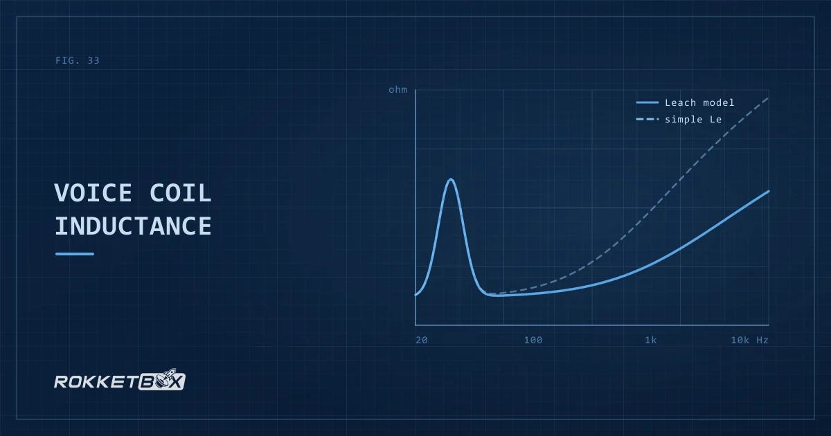
The simplest driver model treats voice coil inductance (Le) as an ideal inductor, whose impedance rises in direct proportion to frequency: double the frequency, double the impedance.
Real voice coils show a high-frequency rise that is shallower. Impedance rises roughly in proportion to the square root of f. That gap matters in three places.
Crossover design
A passive crossover that includes the subwoofer's impedance in the network gets wrong slopes and points if the high-frequency impedance model is wrong.
Impedance minimum
Amplifier compatibility depends on the impedance minimum. An ideal inductor model can overestimate mid-frequency impedance and miss a dip that falls below the amplifier's minimum load.
Power delivery
The impedance curve sets how much current, and therefore power, the amplifier delivers at each frequency. Get it wrong and the simulated SPL doesn't match reality.
Why real coils aren't ideal inductors
A voice coil is wound around a former that sits inside a magnetic gap, right next to the pole piece (the iron core of the magnet). Alternating current in the coil induces eddy currents in the pole piece. Those currents create their own magnetic field that opposes the coil's, which reduces the effective inductance. Eddy currents grow with frequency, so effective inductance falls with frequency, giving the shallower-than-ideal impedance rise.
Some drivers add a shorting ring (a copper or aluminium ring) around the pole piece to strengthen this effect. It gives eddy currents a low-resistance path, reduces effective inductance at high frequencies and flattens the impedance curve. That reduces distortion and improves high-frequency response.
The Leach semi-inductance model
The Leach model replaces the ideal inductor with a semi-inductance element: a resistor in parallel with the inductor (an eddy-current resistance across jwLe). At low frequencies the coil behaves like an inductor and impedance rises with frequency. As frequency climbs, the parallel resistance takes over and the rise flattens toward that resistive value, where an ideal inductor would keep climbing. That flattening rise is what measured coils show.
This captures the eddy current effect far better than the ideal model across the full frequency range. RokketBox derives the parameters automatically from the driver's published Le specification.
What this means in practice
The difference between the two models is most visible above 200 Hz, above a subwoofer's primary operating range. It still matters in three situations.
Impedance-compensated systems. Anything that uses the impedance curve for calculations, such as passive crossovers or amplifier loading analysis, benefits from the correct model.
4th-order bandpass enclosures. The coupled chambers interact through the driver's impedance, so the bandpass response is sensitive to the impedance curve shape. An incorrect inductance model shifts the response.
Impedance matching. When several drivers share one amplifier channel, the combined impedance depends on each driver's full curve. Accurate modelling prevents surprises.
How RokketBox implements it
RokketBox uses the Leach semi-inductance model by default for all driver simulations, so the high-frequency rise on the impedance plot reflects semi-inductance behaviour and not an ideal inductor.
If a driver's T/S parameters include Le (as most do), RokketBox converts it automatically to the Leach semi-inductance parameters, a parallel resistor-inductor network. The result is an impedance curve that matches what you'd measure with a real impedance analyser, unlike the simple-inductor curve many tools draw.
Common questions
What is the Leach voice coil inductance model?
The Leach model replaces the ideal inductor (impedance proportional to frequency) with a semi-inductance element: a resistor in parallel with the inductor. This accurately models the effect of eddy currents in the pole piece, which reduce effective inductance at high frequencies so the impedance rise flattens instead of climbing without limit. The result matches measured impedance curves far better than the ideal model.
Why does voice coil inductance matter for subwoofer simulation?
Accurate inductance modelling affects impedance curves, which determine power delivery, amplifier loading, and crossover behaviour. The ideal inductor model overestimates high-frequency impedance, which can hide impedance dips that fall below amplifier minimums and produce incorrect SPL predictions in bandpass enclosures.